VPU extrinsic calibration
General information
Orientation
ODS uses the IMU to compute the motion of the vehicle. To do this, the VPU needs to be calibrated, using the same reference frame as used for the head calibration.
In the table below, we assume that the VPU is positioned parallel to the coordinate system. We provide the angle correspondence between the VPU position and the rotX, rotY and rotZ values. The translations can be measured directly from CAD drawings or on the vehicle itself.
User coordinate system: X (forward), Y (to the left), Z (up).
rotX [rad] |
rotY [rad] |
rotZ [rad] |
VPU plugs direction |
VPU plugs direction in user coordinates (math.) |
VPU label direction |
VPU label direction in user coordinates (math.) |
|---|---|---|---|---|---|---|
0 |
0 |
0 |
to the right |
-Y |
upwards |
+Z |
0 |
0 |
pi/2 |
to the front |
+X |
upwards |
+Z |
0 |
0 |
pi |
to the left |
+Y |
upwards |
+Z |
0 |
0 |
-pi/2 |
to the back |
-X |
upwards |
+Z |
pi/2 |
0 |
0 |
downwards |
-Z |
to the right |
-Y |
pi/2 |
pi/2 |
0 |
downwards |
-Z |
to the front |
+X |
pi/2 |
pi |
0 |
downwards |
-Z |
to the left |
+Y |
pi/2 |
-pi/2 |
0 |
downwards |
-Z |
to the back |
-X |
pi |
0 |
0 |
to the left |
+Y |
downwards |
-Z |
pi |
0 |
pi/2 |
to the front |
+X |
downwards |
-Z |
pi |
0 |
pi |
to the right |
-Y |
downwards |
-Z |
pi |
0 |
-pi/2 |
to the back |
-X |
downwards |
-Z |
-pi/2 |
0 |
0 |
upwards |
+Z |
to the left |
+Y |
-pi/2 |
pi/2 |
0 |
upwards |
+Z |
to the front |
+X |
-pi/2 |
pi |
0 |
upwards |
+Z |
to the right |
-Y |
-pi/2 |
-pi/2 |
0 |
upwards |
+Z |
to the back |
-X |
0 |
pi/2 |
pi |
to the left |
+Y |
to the front |
+X |
0 |
-pi/2 |
pi |
to the left |
+Y |
to the back |
-X |
0 |
pi/2 |
0 |
to the right |
-Y |
to the front |
+X |
0 |
-pi/2 |
0 |
to the right |
-Y |
to the back |
-X |
-pi/2 |
0 |
pi/2 |
to the front |
+X |
to the left |
+Y |
pi/2 |
0 |
pi/2 |
to the front |
+X |
to the right |
-Y |
-pi/2 |
0 |
-pi/2 |
to the back |
-X |
to the left |
+Y |
pi/2 |
0 |
-pi/2 |
to the back |
-X |
to the right |
-Y |
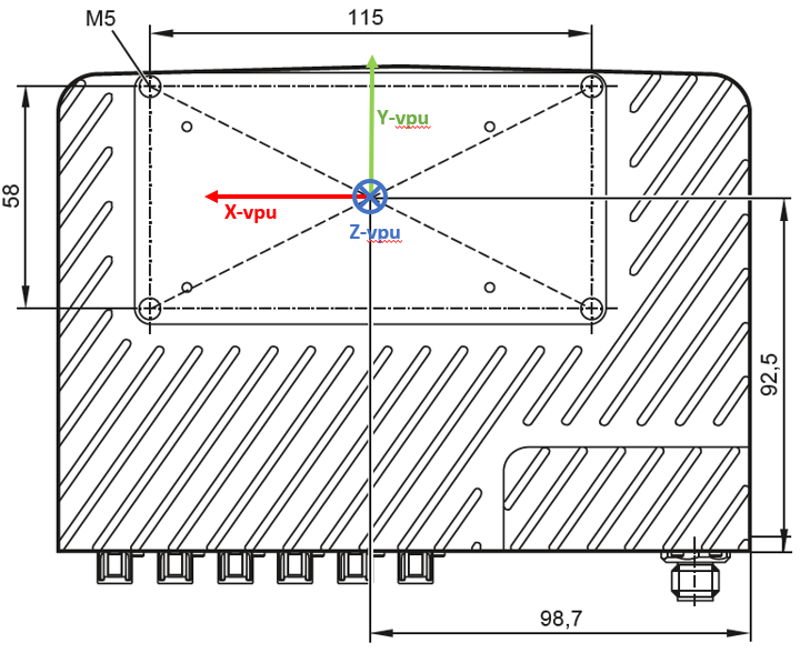
Reference point
The geometrical reference point of the VPU is the intersection point of the two lines of diagonally opposing mounting points at the back of the VPU. See the figure below for reference.
