VPU extrinsic calibration
General Information
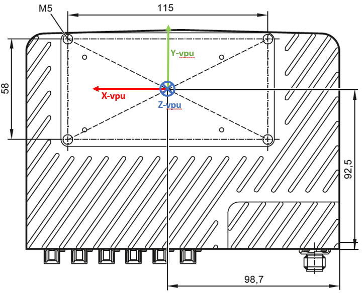
Orientation
The ODS application uses the IMU inside the VPU to compute vehicle motion. To enable this, the VPU must be extrinsically calibrated using the same reference frame as used for the camera head calibration.
Note
The extrinsic calibration of the VPU is **only relevant for the ODS application**. This calibration does **not** affect the raw IMU output provided on Port 6. Therefore, if you are using the IMU data independently (e.g., for custom applications), the VPU calibration will have no impact.
In the table below, we assume the VPU is aligned with the coordinate system. The table provides the angle correspondence between the VPU’s orientation and the rotX, rotY, and rotZ values. Translations should be measured directly from CAD drawings or the physical installation on the vehicle.
VPU coordinate system
User coordinate system: X (forward), Y (to the left), Z (up).
rotX [rad] |
rotY [rad] |
rotZ [rad] |
VPU plugs direction |
VPU plugs direction in user coordinates (math.) |
VPU label direction |
VPU label direction in user coordinates (math.) |
|---|---|---|---|---|---|---|
0 |
0 |
0 |
to the right |
-Y |
upwards |
+Z |
0 |
0 |
pi/2 |
to the front |
+X |
upwards |
+Z |
0 |
0 |
pi |
to the left |
+Y |
upwards |
+Z |
0 |
0 |
-pi/2 |
to the back |
-X |
upwards |
+Z |
pi/2 |
0 |
0 |
downwards |
-Z |
to the right |
-Y |
pi/2 |
pi/2 |
0 |
downwards |
-Z |
to the front |
+X |
pi/2 |
pi |
0 |
downwards |
-Z |
to the left |
+Y |
pi/2 |
-pi/2 |
0 |
downwards |
-Z |
to the back |
-X |
pi |
0 |
0 |
to the left |
+Y |
downwards |
-Z |
pi |
0 |
pi/2 |
to the front |
+X |
downwards |
-Z |
pi |
0 |
pi |
to the right |
-Y |
downwards |
-Z |
pi |
0 |
-pi/2 |
to the back |
-X |
downwards |
-Z |
-pi/2 |
0 |
0 |
upwards |
+Z |
to the left |
+Y |
-pi/2 |
pi/2 |
0 |
upwards |
+Z |
to the front |
+X |
-pi/2 |
pi |
0 |
upwards |
+Z |
to the right |
-Y |
-pi/2 |
-pi/2 |
0 |
upwards |
+Z |
to the back |
-X |
0 |
pi/2 |
pi |
to the left |
+Y |
to the front |
+X |
0 |
-pi/2 |
pi |
to the left |
+Y |
to the back |
-X |
0 |
pi/2 |
0 |
to the right |
-Y |
to the front |
+X |
0 |
-pi/2 |
0 |
to the right |
-Y |
to the back |
-X |
-pi/2 |
0 |
pi/2 |
to the front |
+X |
to the left |
+Y |
pi/2 |
0 |
pi/2 |
to the front |
+X |
to the right |
-Y |
-pi/2 |
0 |
-pi/2 |
to the back |
-X |
to the left |
+Y |
pi/2 |
0 |
-pi/2 |
to the back |
-X |
to the right |
-Y |
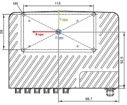
Reference point
The geometrical reference point of the VPU is the intersection point of the two lines of diagonally opposing mounting points at the back of the VPU. See the figure below for reference.