LEDs
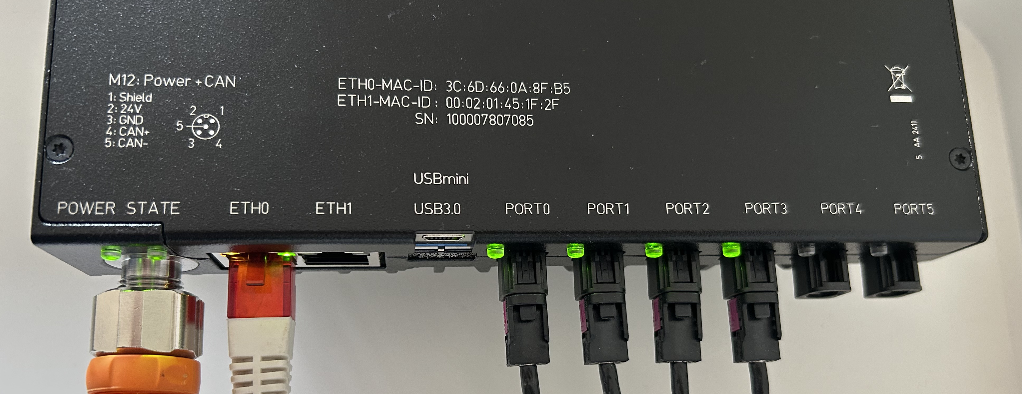
The VPU has eight LEDs for POWER, STATE, PORT[0…5] that light up red or green depending on the status of the system.
Power LED
LED |
Red |
Green |
Description |
|---|---|---|---|
Power |
N/A |
VPU powered up |
The VPU is powered up with 24V. |
State LED
LED |
Red |
Green |
Description |
|---|---|---|---|
State |
OFF |
OFF |
The VPU is not powered up. |
OFF |
Blinking |
Initialization. |
|
OFF |
ON |
Operate. |
|
Blinking |
OFF |
Critical error. |
|
ON |
OFF |
Major error. |
|
Blinking* |
Blinking* |
Software update. |
Port LEDs
LED |
Green |
Description |
|---|---|---|
Local port LED |
ON |
The VPU is operating and the port is functional (camera head detected). |
Blinking |
Critical or major error related to this port. |
|
OFF |
If the VPU is operating and the port LED is OFF, the port is not functional (no camera head is detected). |
|
Port LED array |
“Knight rider”: port LEDs blinking one after the other. |
Boot-up or initialization sequence. |
Synchronous blinking |
Critical or major system-wide error. |
Ethernet LEDs
Each Ethernet port has two LEDs. The leftmost one, LED 0 below, is yellow. The rightmost one, LED 1 below, is green. They behave the same for both port.
LED |
State |
Description |
|---|---|---|
LED 0 (yellow) |
OFF |
The VPU is not powered-up. |
Blinking |
Initialization sequence. |
|
LED 1 (green) |
OFF |
The VPU is not powered-up. |
Blinking |
Initialization sequence. |